When you build a complex device like a Vocoder in combination with 2 x B&K band filters, it is inevitable to document the configuration. “Always be kind for your future self”. In other words, I made new documentation of the Vocoder, which I will share with you and myself.
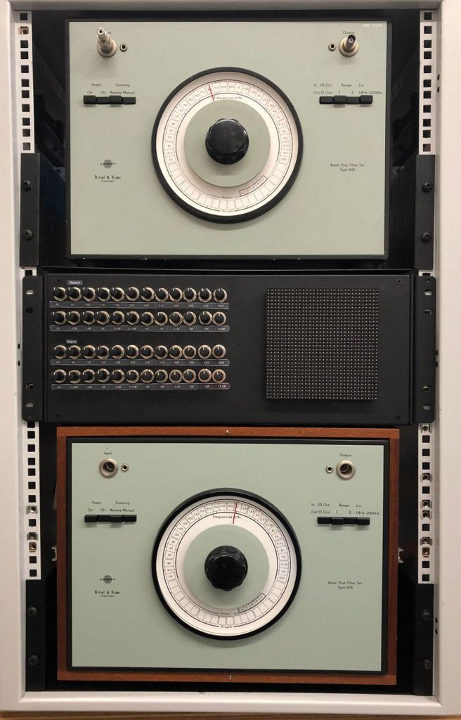
The two B&K filters and the 19″ rack with electronics in between. The electronics is stacked into one big 19″ cabinet and it actually is quiet full with wires, connectors, printed circuit board, fuses and power supplies. If the electronic setup needs to be adjusted, I need a roadmap of all the connections. I chopped all the different functions in the design into parts and I refer to the letters A,B,C until H.
To refresh the setup of the Vocoder, the following overview:
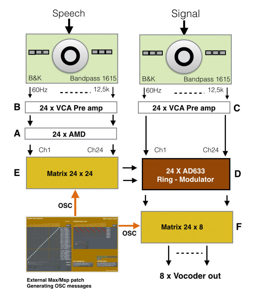
In the explanation of the roadmap I will refer to letters A, B … until H.
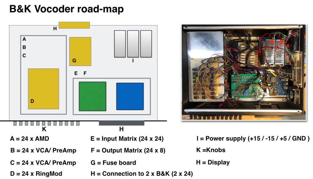
On the right side the actual inside of the 19″ housing and on the left side a reference to all the different functions. To make efficient use of the available space, I stacked all the pcb’s in four layers. These are A, B, C and D.

Which input is located where on the PCB. That is for me the most important part of the documentation. In this way I can find my way around when we have to modify or repair the electronics. So the connections of the 24 times AMD. The layout of the pcb itself can be found here
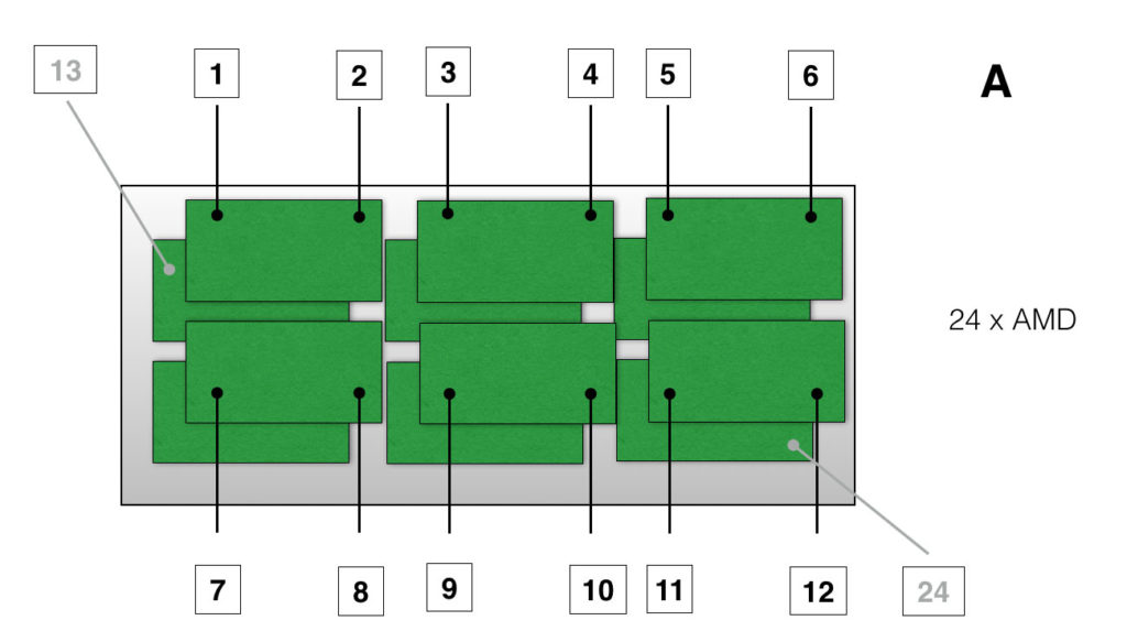
Every AMD printed circuit board has two AMD’s onboard. Since I need 24 Amplitude Demodulators, I had to mount and connect 12 boards in total. The top 6 pcbs cover input 1 -12 and the lower ones 13 -24 (grayed out).
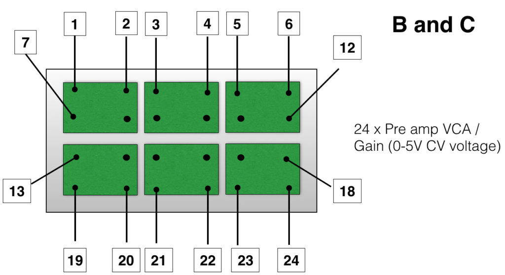
The next two layers consist of 48 x pre-amp, or B and C. The signals coming form the the filters need to be buffered and conditioned (amplified or attenuated). Also the design of the PCB can be found here
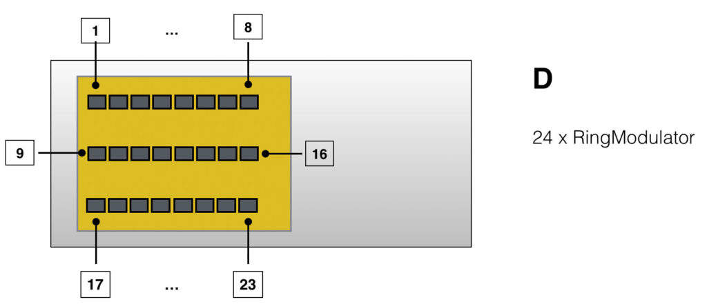
The top layer of the PCB stack, are the 24 times ring-modulator, referred to as D in the layout.
To be able to switch all the in’s and out’s, the Vocoder is designed around two big matrix setups, E and F. Martrix setup E is the matrix of 24 inputs and 24 outputs, that connects the two signals ‘Speech’ and ‘Signal’ together, creating the specific vocoder sounds. Since the matrix chip, the AD75019 only has 16 in’s and 16 out’s (16×16) we have to applpy more chips. To be able to switch 24×24, we need 4 matrices.
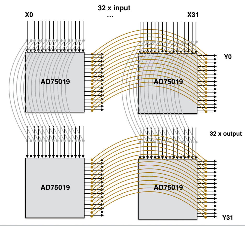
A few years ago I already made a design for a PCB where I could mount and route two AD75019 chips. So when I need 4 of the chips to be connected like the figure above, I need two boards. This is shown below(E):

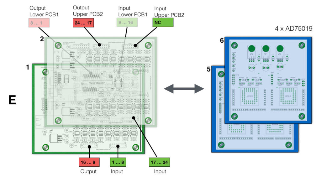
On the left two ‘CompLex’ boards (green) ( 1 and 2) with 16 in and 16 out. I use the these CompLex boards because they already have the right amount of (inverting) opamp implemented, so the summing function as well as the output drive can be used. On the right the 4 matrices (2 x blue) creating a total matrix of 32×32, from which we use only 24×24.
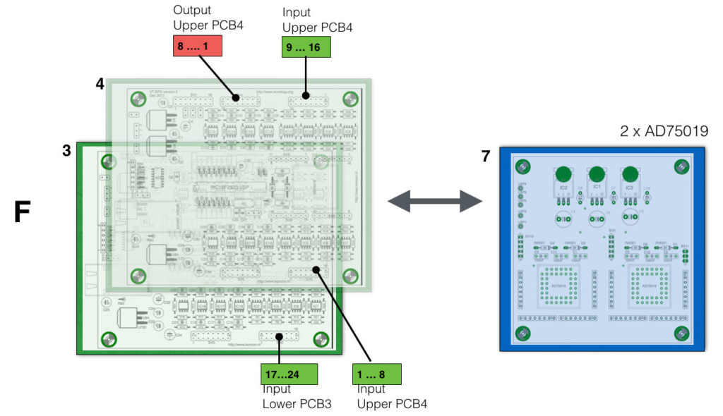
With the output matrix (F) we only need one (blue) board.
‘G’ indicates a fuse-board. This is a board has multiple fuses connected between the different boards (A, B …) and the massive power supply (+15V/2000mA, -15V/2000mA, +5V/7000mA). To avoid ‘fire’ or damage when something on a board goes wrong, the application of a fuse-board is absolutely necessary.
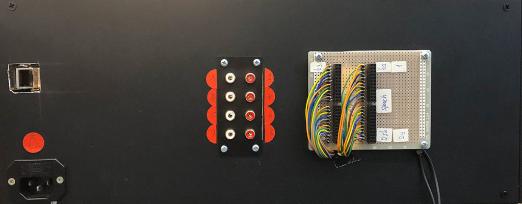
The backside of the Vocoder has connections for the two B&K outputs, 8 vocoder outputs, the mains power-supply and the connection for the LAN cable.
The display of the Vocoder is still under construction (K)- that is, the programming of the whole thing. My colleague Andrea Vogrig is taking care of this part of the project. The display is a 32×32 RGB led display

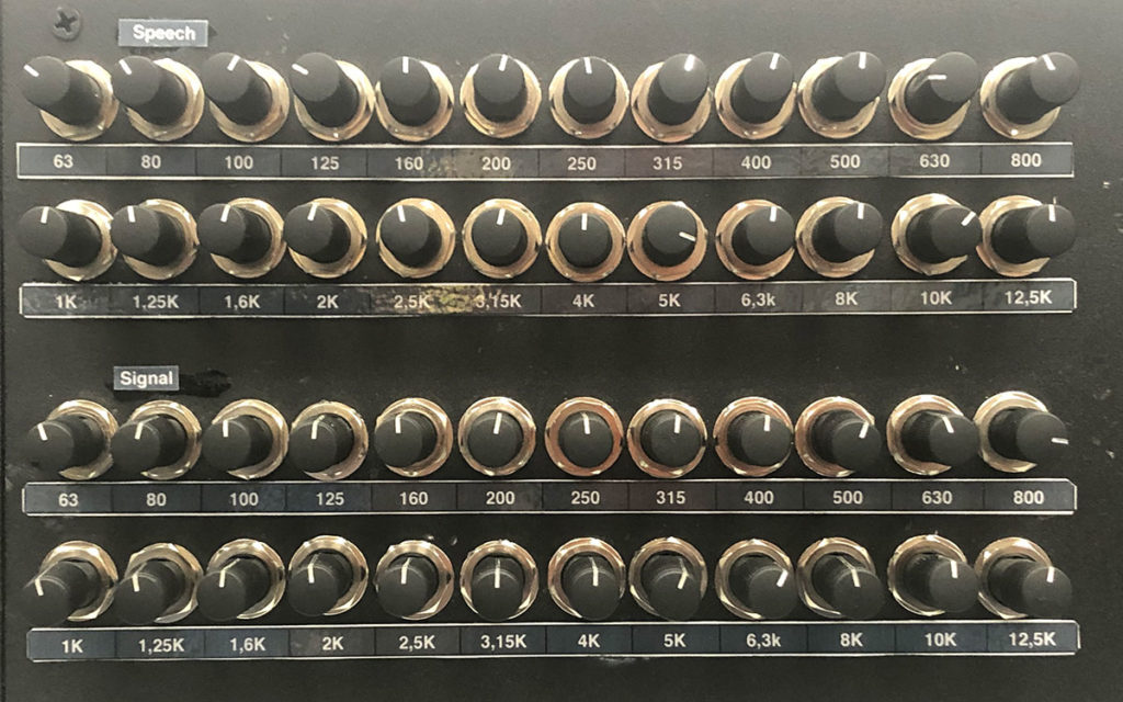
‘K’ is referring to the knobs. There are 48 knobs in total. 24 for the spectrum of the speech input and 24 for the spectrum of the input-signal. The circuit of the VCA is explained here. These 48 potentiometers generate a voltage between 0V-5V, driving the onboard VCA’s. The great idea behind this setup is that in future the 48 VCA’s can be driven by external voltages as well. For now this is not implemented yet.
Last but not least I share a video clip which gives you an indication of the sound of the Vocoder. I recorded it simply with my iPhone and the speech signal is from the book ‘Junky, by William S. Burroughs’. When the vocoder is completely finished, I will make a better video. For now its a great indication.
